To study the acceptance of the spectrometers, we
used a tracking program provided by the Beams Division. [36]
This program
tracks particles through each element of the lattice, using the measured
lengths and magnetic fields of the elements. The Run II beam energy of
1 TeV was assumed in the lattice calculations. The user provides the initial
conditions of the proton (x, y, c![]() t, x', y',
t, x', y', ![]() )
and the program
gives the six-vector as a function of longitudinal distance from the
interaction point.
)
and the program
gives the six-vector as a function of longitudinal distance from the
interaction point.
Several iterations of the acceptance studies have been performed. Initial studies used a 1 TeV version of the Run I lattice. Subsequent studies involved moving the quadrupoles to simulate the desired Run II conditions, and then switching to the proposed Run II dispersion-free lattice [37]. The final studies shown here were done using a modified version of the dispersion-free lattice, as moving the quadrupoles necessitates a few percent change in the gradients in order to properly retune the Tevatron [37].
The acceptance is critically dependent on the distance
of the detector from the beam axis, which depends on the beam width
(![]() ).
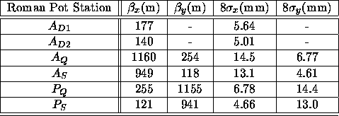
). Table 1, which is extracted from a detailed study
of the background from accelerator losses [38],
shows the beta function and corresponding 8
Table 1, which is extracted from a detailed study
of the background from accelerator losses [38],
shows the beta function and corresponding 8![]() beam widths
at the proposed Roman pot locations (dipole pots are only
useful in the horizontal plane).
Normalized emittances of 3
beam widths
at the proposed Roman pot locations (dipole pots are only
useful in the horizontal plane).
Normalized emittances of 3 ![]() for protons and
2.2
for protons and
2.2 ![]() for anti-protons were assumed, but the
larger 8
for anti-protons were assumed, but the
larger 8![]() proton widths were used in Table 1.
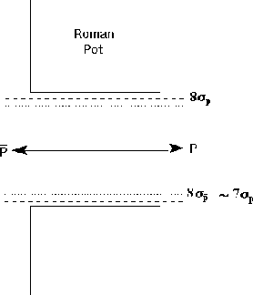
Figure 11 shows a sketch of a pair of
pots located at 8
proton widths were used in Table 1.
Figure 11 shows a sketch of a pair of
pots located at 8![]() from the
proton beam for the case of no separation of beams (both beams have the same
axis), which is the situation for the quadrupole spectrometers.
The pot displacement is clearly limited by the wider proton beam,
not the
from the
proton beam for the case of no separation of beams (both beams have the same
axis), which is the situation for the quadrupole spectrometers.
The pot displacement is clearly limited by the wider proton beam,
not the ![]() beam for which
beam for which ![]() .
.
The 8![]() beam width
over the entire distance from the interaction point through the
pot locations is shown in Fig. 12. Roman pots placed
at 8
beam width
over the entire distance from the interaction point through the
pot locations is shown in Fig. 12. Roman pots placed
at 8![]() from the beam could detect
scattered p's and
from the beam could detect
scattered p's and ![]() 's with displacements larger than than
this.
A comparison of the Q and S rows of the table for p's and
's with displacements larger than than
this.
A comparison of the Q and S rows of the table for p's and ![]() 's
reveals that
for this lattice the horizontal plane for protons is equivalent
to the vertical plane for
's
reveals that
for this lattice the horizontal plane for protons is equivalent
to the vertical plane for ![]() 's and vice versa. This point will be
discussed further in Sec. 3.3.2 and leads to the ``cross'' design
mentioned earlier.
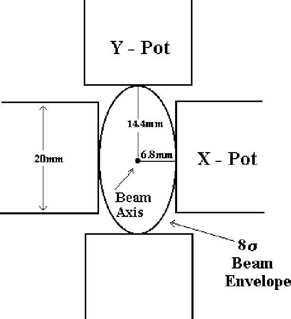
Figure 13 shows a
cross section sketch of the four
's and vice versa. This point will be
discussed further in Sec. 3.3.2 and leads to the ``cross'' design
mentioned earlier.
Figure 13 shows a
cross section sketch of the four ![]() pots inserted at
pots inserted at ![]() from the beam axis.
from the beam axis.

Table 1: ![]() -functions and
-functions and ![]() positions at the Roman pot
locations.
positions at the Roman pot
locations.

Figure 11: The ![]() proton and anti-proton beam
widths are shown for the case of no beam separation.
The closest approach of the pots is limited by the proton
beam width.
proton and anti-proton beam
widths are shown for the case of no beam separation.
The closest approach of the pots is limited by the proton
beam width.

Figure 12: The ![]() proton beam envelopes
are shown for (a) the horizontal plane and (b)
the vertical plane as a function of distance from the interaction point.
The pot locations are marked in the figure.
proton beam envelopes
are shown for (a) the horizontal plane and (b)
the vertical plane as a function of distance from the interaction point.
The pot locations are marked in the figure.

Figure 13: A cross section view of the four ![]() pots (only the active area is shown). The pots are inserted
at 8
pots (only the active area is shown). The pots are inserted
at 8![]() from the beam axis, and are thus tangent to the
8
from the beam axis, and are thus tangent to the
8![]() proton beam profile.
proton beam profile.
The tracking program is used to map out the acceptance in |t| and ![]() .
For a track to be accepted, it must remain within the beam
pipe (inner radius of 35 mm) and within the separator aperture (25 mm).
It must also
pass through the active area of the detector in both pots, which
is assumed to cover
.
For a track to be accepted, it must remain within the beam
pipe (inner radius of 35 mm) and within the separator aperture (25 mm).
It must also
pass through the active area of the detector in both pots, which
is assumed to cover ![]() mm and -10<y<10 mm for horizontal
pots (x and y are interchanged for vertical pots). The
mm and -10<y<10 mm for horizontal
pots (x and y are interchanged for vertical pots). The
![]() (
(![]() ) values are obtained from the
) values are obtained from the ![]() (
(![]() ) column in Table 1.
) column in Table 1.
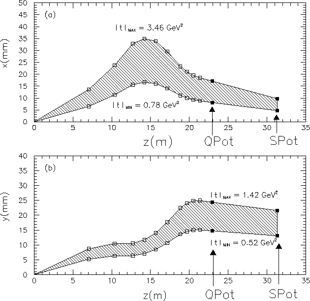
An example of the results of the tracking program is given in
Fig. 14, which shows trajectories of protons
with ![]() (corresponding to
(corresponding to ![]() ).
Figure 14(a)
shows the displacement in x with y=0
as a function of the distance in z from the interaction point.
The shaded region shows the range of momentum transfers accepted by
quadrupole spectrometer pots placed at 8
).
Figure 14(a)
shows the displacement in x with y=0
as a function of the distance in z from the interaction point.
The shaded region shows the range of momentum transfers accepted by
quadrupole spectrometer pots placed at 8![]() beam widths from the
beam axis.
Figure 14(b) shows the displacement in y with x=0.
The minimum trajectory is typically limited by the displacement of the
S pot, while the maximum trajectory is limited by the beam pipe
in Fig. 14(a) and the separator aperture in Fig. 14(b).
For reference, momentum transfers of |t|=0.5
and |t|=3.5 GeV
beam widths from the
beam axis.
Figure 14(b) shows the displacement in y with x=0.
The minimum trajectory is typically limited by the displacement of the
S pot, while the maximum trajectory is limited by the beam pipe
in Fig. 14(a) and the separator aperture in Fig. 14(b).
For reference, momentum transfers of |t|=0.5
and |t|=3.5 GeV![]() correspond to angles of 0.7 and 1.9 mrad, respectively.
Details of the acceptance are discussed later in this section.
correspond to angles of 0.7 and 1.9 mrad, respectively.
Details of the acceptance are discussed later in this section.

Figure 14:
The trajectory of a proton with ![]() is shown for the range
of momentum transfer accepted by pots at a displacement of 8
is shown for the range
of momentum transfer accepted by pots at a displacement of 8![]() beam
widths from the beam axis.
(a) shows the x displacement from the beam axis
for y=0 versus the distance in z from the interaction point (b) shows
the y displacement for x=0. Larger values for
beam
widths from the beam axis.
(a) shows the x displacement from the beam axis
for y=0 versus the distance in z from the interaction point (b) shows
the y displacement for x=0. Larger values for ![]() can be
obtained when the requirement that the scattering take place in only
one plane is relaxed.
can be
obtained when the requirement that the scattering take place in only
one plane is relaxed.
The acceptance is maximized by minimizing the distance between the
detectors and the beam axis.
This distance is limited primarily by the halo rates
which increase as the pots are inserted closer to the
beam. Using an initial intensity of
 ![]() protons per bunch,
we have determined that the beam halo rates
for an 8
protons per bunch,
we have determined that the beam halo rates
for an 8![]() pot location are
on the order of
pot location are
on the order of ![]() protons/second in the quadrupole
pots [38], and a factor of two higher in the dipole pots.
The halos rates decrease by about a factor of three at 9
protons/second in the quadrupole
pots [38], and a factor of two higher in the dipole pots.
The halos rates decrease by about a factor of three at 9![]() and quickly decrease with larger pot displacements.
There is some dependence on the assumptions and exact collimation
scheme, which has not been tuned to minimize the rates at
the pot positions.
With a crossing rate of 1.7 MHz, a 100 kHz halo rate
implies that one out of every 10-20 crossings will have a hit from halo.
Details of the effect of halo backgrounds are given in Sec 5.3.2, and
this magnitude of the halo background is determined to be acceptable.
The real rates will have to be measured and the exact pot displacements
will then be determined. The current studies indicate that a reasonable
pot location is between 8 and 9
and quickly decrease with larger pot displacements.
There is some dependence on the assumptions and exact collimation
scheme, which has not been tuned to minimize the rates at
the pot positions.
With a crossing rate of 1.7 MHz, a 100 kHz halo rate
implies that one out of every 10-20 crossings will have a hit from halo.
Details of the effect of halo backgrounds are given in Sec 5.3.2, and
this magnitude of the halo background is determined to be acceptable.
The real rates will have to be measured and the exact pot displacements
will then be determined. The current studies indicate that a reasonable
pot location is between 8 and 9![]() for quadrupole pots and 10
for quadrupole pots and 10![]() for dipole pots.
for dipole pots.