The nominal ![]() values for dipole spectrometer pot locations are
obtained by scaling the
values for dipole spectrometer pot locations are
obtained by scaling the ![]() values from
Table 1 and give an
values from
Table 1 and give an ![]() of 7.0 mm and 6.3 mm, for
of 7.0 mm and 6.3 mm, for
![]() and
and ![]() , respectively. An anti-proton is considered to be
accepted by the dipole spectrometer if it
passes through the active area of both detectors while remaining within
the limiting aperture of the beam pipe throughout its entire trajectory.
The acceptance is determined as a function of the initial conditions of
the anti-proton (
, respectively. An anti-proton is considered to be
accepted by the dipole spectrometer if it
passes through the active area of both detectors while remaining within
the limiting aperture of the beam pipe throughout its entire trajectory.
The acceptance is determined as a function of the initial conditions of
the anti-proton (![]() , |t|, and
, |t|, and ![]() ).
).
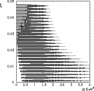
The geometric (![]() ) acceptance of the dipole spectrometer is shown in
bins of
) acceptance of the dipole spectrometer is shown in
bins of ![]() and |t| in Fig. 15. The size of the boxes
are proportional to the geometric acceptance with the largest boxes representing
100% acceptance. The acceptance is especially good for
0<|t|<0.5 GeV
and |t| in Fig. 15. The size of the boxes
are proportional to the geometric acceptance with the largest boxes representing
100% acceptance. The acceptance is especially good for
0<|t|<0.5 GeV![]() and high
and high ![]() (
(![]() ). At low |t| and
). At low |t| and
![]() the particle is not deflected enough to enter the pots, while at
high |t| and
the particle is not deflected enough to enter the pots, while at
high |t| and ![]() the particle is deflected too much and scatters off
the beam pipe.
the particle is deflected too much and scatters off
the beam pipe.

Figure 15: The geometric acceptance in bins of ![]() and |t|
for the dipole spectrometer with the detectors
at the nominal
and |t|
for the dipole spectrometer with the detectors
at the nominal ![]() displacements. The acceptance in each bin
is proportional to the size of the box, with the largest box
representing 100% acceptance.
displacements. The acceptance in each bin
is proportional to the size of the box, with the largest box
representing 100% acceptance.
We calculate the total acceptance (or cross section times acceptance,
![]() )
by integrating over the
)
by integrating over the ![]() and
|t| values accepted by the pots. We include the |t| dependence
using the relation
and
|t| values accepted by the pots. We include the |t| dependence
using the relation ![]() , where
, where ![]() from
Ref. [21]. This expression is valid for single diffractive and
most likely double pomeron events, but for elastic events
from
Ref. [21]. This expression is valid for single diffractive and
most likely double pomeron events, but for elastic events
![]() [22].
The total acceptance
is dominated by the |t| acceptance, since the cross section
falls so steeply with |t|.
[22].
The total acceptance
is dominated by the |t| acceptance, since the cross section
falls so steeply with |t|.
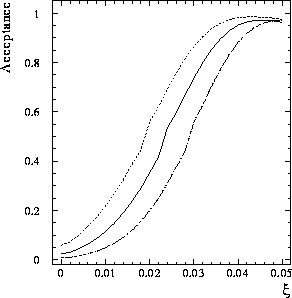
The solid line in Fig. 16
shows the total acceptance for diffractive events
for ![]() pot positions. For comparison, the
acceptance for pot positions of
pot positions. For comparison, the
acceptance for pot positions of ![]() (dashed line)
and
(dashed line)
and ![]() (dotted line) are also shown.
The acceptance increases rapidly with increasing
(dotted line) are also shown.
The acceptance increases rapidly with increasing ![]() for all
pot displacements. Even for
for all
pot displacements. Even for ![]() there is still acceptance at
low
there is still acceptance at
low ![]() . The
. The ![]() acceptance for several
acceptance for several ![]() and
and ![]() values is summarized
in Table 2. Although we are only focussing on the acceptance
for
values is summarized
in Table 2. Although we are only focussing on the acceptance
for ![]() , the dipole spectrometer retains
, the dipole spectrometer retains ![]() acceptance up to
acceptance up to
![]() .
.

Table 2: Integrated total acceptance (in percent) for anti-protons
using a ![]() Roman pot displacement in the horizontal plane versus
Roman pot displacement in the horizontal plane versus
![]() and
and ![]() .
.

Figure 16: The total acceptance as a function of ![]() for
the nominal
for
the nominal ![]() pot displacements (solid line).
The acceptance is integrated over |t| and
pot displacements (solid line).
The acceptance is integrated over |t| and ![]() and assumes
a single diffractive |t| dependence as discussed in the text.
For reference, the acceptance for
and assumes
a single diffractive |t| dependence as discussed in the text.
For reference, the acceptance for ![]() (dashed line) and
(dashed line) and ![]() (dotted line) are also shown.
(dotted line) are also shown.
It was mentioned earlier that CDF had little acceptance for ![]() .
This was due to several factors [39]:
.
This was due to several factors [39]:
The situation for the DØ dipole spectrometer will be much improved.
The design we are considering for our pots, discussed in Sec. 4.1
should result in a dead area on the order of 100 ![]() m, instead
of a few millimeters. The separation
of the beams is more advantageous at the DØ location, with the
m, instead
of a few millimeters. The separation
of the beams is more advantageous at the DØ location, with the ![]() \
beam located 0.3 mm closer to the pots than the proton beam [40].
We will be preparing for a long run and will have adequate time to
study the halo rates in order to minimize the pot displacement.
The long running period will allow us to obtain large data samples
even if the acceptance were significantly less than 1%.
We consequently expect to have acceptance to
\
beam located 0.3 mm closer to the pots than the proton beam [40].
We will be preparing for a long run and will have adequate time to
study the halo rates in order to minimize the pot displacement.
The long running period will allow us to obtain large data samples
even if the acceptance were significantly less than 1%.
We consequently expect to have acceptance to ![]() near zero, as shown
in Fig. 16.
near zero, as shown
in Fig. 16.
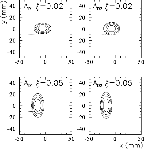
To better understand the acceptance, it is instructive
to study Fig. 17, which shows the horizontal and vertical
displacements at the ![]() and
and ![]() pot locations for scattered
pot locations for scattered
![]() 's with
's with ![]() (top plots) and
(top plots) and ![]() (bottom plots).
The ellipses are contours of constant |t| ranging from 0.5 GeV
(bottom plots).
The ellipses are contours of constant |t| ranging from 0.5 GeV![]() for
the inner-most ellipse to 2.0 GeV
for
the inner-most ellipse to 2.0 GeV![]() for the outer-most ellipse.
The ellipses are displaced in the negative x direction due to the
bending into the Tevatron ring of particles with less than the beam momentum.
Comparing the ellipses for
for the outer-most ellipse.
The ellipses are displaced in the negative x direction due to the
bending into the Tevatron ring of particles with less than the beam momentum.
Comparing the ellipses for ![]() and
and ![]() shows that this
deflection is larger for higher
shows that this
deflection is larger for higher ![]() (lower
(lower ![]() momentum) as expected.
The dashed bracket (superimposed on
momentum) as expected.
The dashed bracket (superimposed on ![]() locations)
represents a detector at the proposed
locations)
represents a detector at the proposed ![]() displacement.
It clearly intercepts a large portion of
the ellipses, including the critical low |t|
values. A detector with a displacement of 13 mm
shown by the dotted bracket on the
displacement.
It clearly intercepts a large portion of
the ellipses, including the critical low |t|
values. A detector with a displacement of 13 mm
shown by the dotted bracket on the ![]() plots will
clearly have much worse acceptance.
plots will
clearly have much worse acceptance.

Figure 17: The x and y displacements
at the ![]() (left plots) and
(left plots) and
![]() (right plots) pot locations are shown as contours of constant |t|,
ranging from 0.5-2.0 GeV
(right plots) pot locations are shown as contours of constant |t|,
ranging from 0.5-2.0 GeV![]() (smaller |t| gives smaller
displacement) for
(smaller |t| gives smaller
displacement) for ![]() (top plots) and 0.05 (bottom plots).
The dashed brackets show a pot displacement of 6.3 mm (10
(top plots) and 0.05 (bottom plots).
The dashed brackets show a pot displacement of 6.3 mm (10![]() ), while
the dotted brackets show a pot displacement of 13 mm (CDF Run I position).
), while
the dotted brackets show a pot displacement of 13 mm (CDF Run I position).