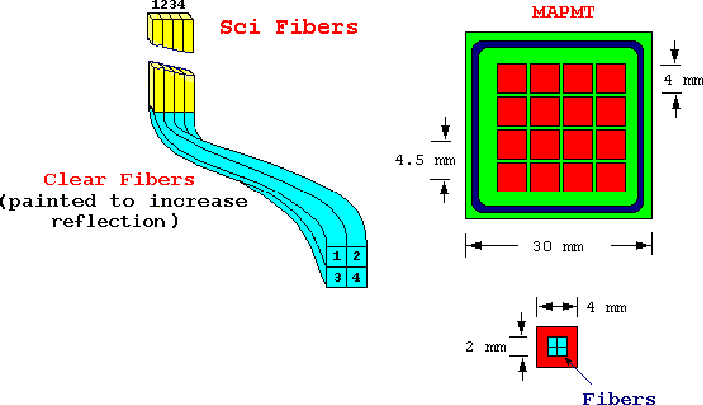
Figure 26: The interface of clear and scintillating fibers and the MAPMT.
The scintillating fibers are connected to clear fibers that are bundled together in groups of four and connected to one channel of the MAPMT as shown in Fig. 26. Four fibers per channel will give about 10 photoelectrons and fit comfortably within the pixel size of the MAPMT. There will be 112 channels per pot, so seven 16 channel tubes will be required for each pot (126 in all). The upper right side of Fig. 26 shows a front view of the 16 channel HAMAMATSU H6568 MAPMT. This MAPMT presents good gain uniformity among its 16 anodes with negligible cross-talk and has a pitch of 4.5 mm. The lower right part of the figure shows how the four fiber arrangement interfaces with an anode.
![]()
Figure 26: The interface of clear and scintillating fibers
and the MAPMT.
The MAPMT's can be read out by a standard Central Fiber Tracker
(CFT) trigger board, with one trigger board required
for each of the nine spectrometers.
The total number of channels needed per spectrometer is 224 (112 per pot)
which is well below the trigger board limit of 512 channels.
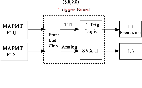
A schematic of the trigger board as applied
to the outputs for the ![]() spectrometer is shown in Fig. 27.
The signal from the MAPMT will likely have to
be attenuated by at least a factor of ten since the gain
expected from the MAPMT is much greater than that of the VLPC,
for which the boards were designed. The
signals will be passed through
the existing front-end chip, modulo the
minor modifications to the components necessitated by the
exact signal size and shape. These boards were designed
to allow for different input signals since they are being used by the
central and forward preshower detectors in addition to the central fiber
tracker, thus the modification of these components will not be difficult
or costly.
The front-end chip outputs signals to the SVX-II chip for digitization.
The SVX-II chip will then store the information
from the fiber hits in the standard event data block. The front-end chip
also outputs a TTL signal for use in the trigger logic.
spectrometer is shown in Fig. 27.
The signal from the MAPMT will likely have to
be attenuated by at least a factor of ten since the gain
expected from the MAPMT is much greater than that of the VLPC,
for which the boards were designed. The
signals will be passed through
the existing front-end chip, modulo the
minor modifications to the components necessitated by the
exact signal size and shape. These boards were designed
to allow for different input signals since they are being used by the
central and forward preshower detectors in addition to the central fiber
tracker, thus the modification of these components will not be difficult
or costly.
The front-end chip outputs signals to the SVX-II chip for digitization.
The SVX-II chip will then store the information
from the fiber hits in the standard event data block. The front-end chip
also outputs a TTL signal for use in the trigger logic.

Figure 27: A schematic diagram of the readout of the scintillating fiber
detectors.
The Level 1 trigger logic is formed in gate array chips which
combine the hit plane information along with a table-lookup
incorporating the transport matrix equations
to give the ![]() and |t| of the track.
A preliminary study of the tracking equations indicates that about
500 equations will be necessary to specify a typical
and |t| of the track.
A preliminary study of the tracking equations indicates that about
500 equations will be necessary to specify a typical ![]() and |t|
range, well below the 8000 equations available on the trigger board.
The total time required for the FPD Level 1 decision is about 800 nsec,
400 nsec for proton transit and return of the signal to the DØ\
region and another 400 nsec for the trigger logic and transit to
the Level 1 framework. This is well within the
4.2
and |t|
range, well below the 8000 equations available on the trigger board.
The total time required for the FPD Level 1 decision is about 800 nsec,
400 nsec for proton transit and return of the signal to the DØ\
region and another 400 nsec for the trigger logic and transit to
the Level 1 framework. This is well within the
4.2  time allowed for a Level 1 decision.
The Level 1 framework will automatically synchronize the FPD decision
with all other Level 1 decisions, so timing will not be a problem.
The nine CFT trigger cards (one for each spectrometer) will transmit their trigger decisions to the FPD trigger manager. The manager will combine these independent trigger decisions into L1 ``and/or'' terms for the L1 Framework. The FPD trigger manager will be housed in a single crate. This crate will be a smaller version of the CFT and Muon L1 trigger managers and will not require additional design or engineering.
The trigger operation is best illustrated with a simple example.
Consider a single diffractive interaction trigger
which requires a coincidence of trigger
scintillator hits along with a track in any one of the nine spectrometers.
First, each spectrometer will transmit all signals (MAPMT and trigger
scintillator hits) to the trigger cards. Each card has been preprogrammed
to trigger if the spectrometer scintillator planes show coincident
hits, and if hits in the tracking planes are consistent with a trajectory
that has ![]() and |t| values within a specified range.
A trigger card then reports the occurrence of the
scintillator coincidence and valid track
to the trigger manager.
and |t| values within a specified range.
A trigger card then reports the occurrence of the
scintillator coincidence and valid track
to the trigger manager. The trigger manager then polls all spectrometers to
see if any one of the spectrometers has a valid trigger,
and provides a logical OR of the results to the L1 Framework.
Double pomeron exchange or elastic triggers
would be generated by requiring pairs of spectrometers to trigger.
We expect approximately ten of the 256 Level 1 ``and/or'' terms will be
utilized by the FPD.
This readout system has the great advantage of using existing DØ trigger boards such that the data storage and triggering are completely DØ standard.