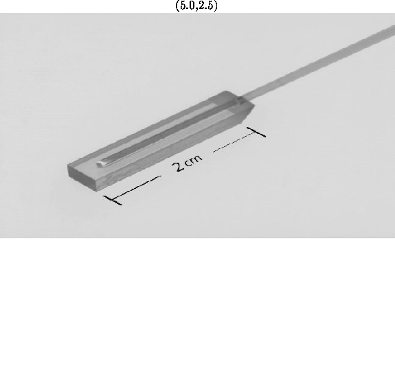
Figure 28: Picture of the detector option showing a wave length shifter (WLS) fiber attached to a piece of plastic scintillator.
We have begun testing of prototype detectors described in the previous section. In the interests of optimizing the detector, we are also studying closely related designs. One possible minor modification to the above design is to use a small piece of plastic scintillator joined to the clear fibers for each channel, rather than making a ribbon with four scintillating fibers.
![]()
Figure 28: Picture of the detector option showing a wave length shifter (WLS)
fiber attached to a piece of plastic scintillator.
Another possibility is to use small scintillator pieces with wavelength shifting fiber (WLS) to collect the light from each channel and guide it to the MAPMT instead of using clear fiber light guides. A single channel with a small grooved piece of plastic scintillator containing a WLS fiber is shown in Fig. 28. The fiber has both ends polished with one end connected to the phototube and the other end sputtered with aluminum to increase reflection and light collection.
This design is attractive since it would reduce the volume occupied by the
fibers in the interior of the pot and also allow thinner fibers ( m)
that have a smaller bending radius. This would imply a reduction of the
pot size and cost.
The 20 channels per detector plane
(either made of a ribbon of fibers or of a
small piece of plastic scintillator) will be assembled in a frame that
will hold them in the correct position and give strength to the
assembly. Figure 29 shows a U channel frame.
The frame was made in a two stage process: first a plastic mold was
made from an aluminum prototype, then the final frame
was cast in polyurathane from the mold.
The frame consists of a series of 850 ![]() m
wide grooves to hold the 800
m
wide grooves to hold the 800 ![]() active detector, with each groove
separated by a 220
active detector, with each groove
separated by a 220 ![]() m fin.
m fin.
In conclusion, testing to optimize the design and study construction issues is underway. The detector technologies are well-known and present no technical risk.
![]()
Figure 29: Picture of the plastic frame designed to align and secure
the individual channels, whether they are
composed of a ribbon of fibers or a small piece of plastic scintillator.