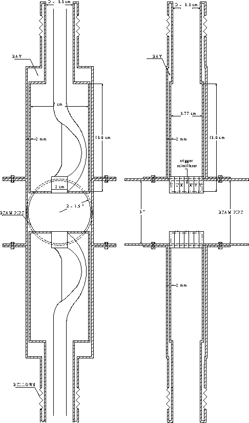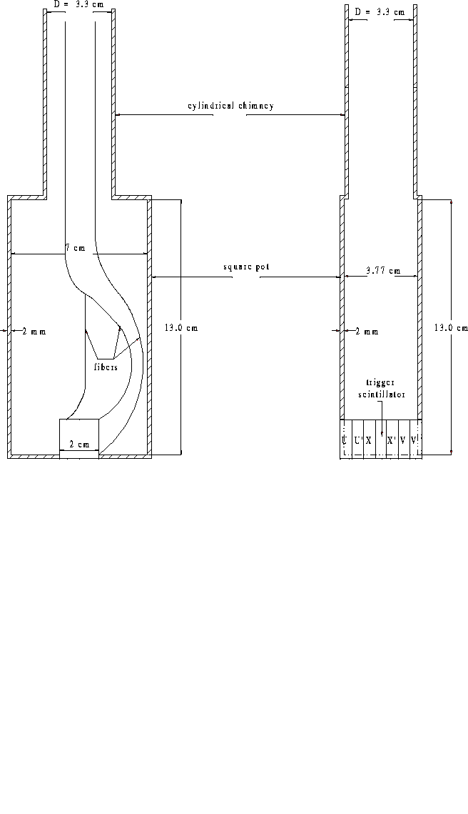
Figure 24: A front and side view of the detector described in the text.

Figure 24: A front and side view of the detector
described in the text.
Figure 24 shows sketches of front and side views
of the Roman pot with the position detector and trigger scintillator.
The trigger scintillator consists of a
 cm plastic scintillator connected to a PMT.
The coincidence formed by the trigger scintillators in each spectrometer
can be used in the Level 1 trigger, both for triggering and rejecting
early time hits from halo.
Existing scintillator and phototubes could be used for these small counters.
We would likely use Level Ø phototubes
from Run I which have a time resolution
of 240 psec, but cannot be used in the upgraded Level Ø due
to the solenoid magnetic field.
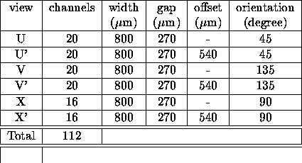
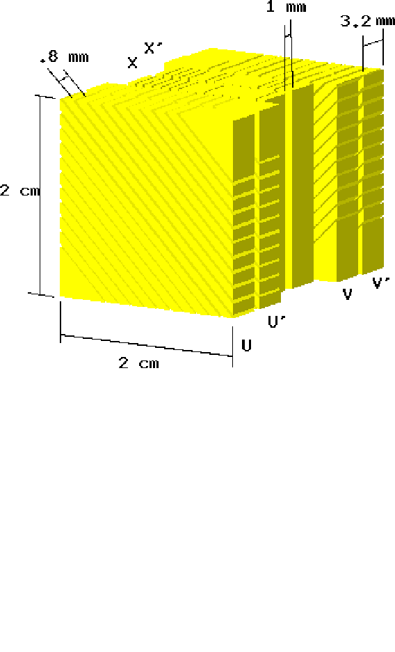
The primary detector option is a six-plane scintillating fiber detector. The detector is comprised of stacked ribbons of four fibers oriented such that the scattered proton (or anti-proton) would pass through all four fibers to maximize the light output. The stacked ribbons have a one-third ribbon width spacing. Each detector will have six views as shown in Fig. 25.
![]()
Table 5: Details of the detector geometry are given,
where gap is the separation between channels,
offset refers to the offset of the primed (')
channels relative to their same view
partners, and orientation is measured relative to the
bottom of the pot.

Figure 25: The six-plane scintillation detector
and frames described in the
text.
The use of  mm square scintillating fibers would allow a
theoretical resolution of about 80
 ![]() m.
The estimated radiation dose of the detector is 0.03 Mrad per year of normal
running. A full hit by the proton beam corresponds to 0.3 Mrad, or ten
years of normal run. Studies have shown that a 1 Mrad dose reduces the
fiber attenuation length to 40% of its original
value [42]. However, due
to the short length of our fibers (2 cm) the reduction in attenuation length
is not important even with several beam accidents.
m.
The estimated radiation dose of the detector is 0.03 Mrad per year of normal
running. A full hit by the proton beam corresponds to 0.3 Mrad, or ten
years of normal run. Studies have shown that a 1 Mrad dose reduces the
fiber attenuation length to 40% of its original
value [42]. However, due
to the short length of our fibers (2 cm) the reduction in attenuation length
is not important even with several beam accidents.